.webp)
A modern cutting machine can pick up a printed sheet, find exactly where the design is, correct for the sheet being slightly crooked, and cut a perfect outline around every sticker – all without the operator measuring anything. That isn't magic; it's smart cutting technology.
In this article, Skycut India looks under the hood: how camera vision reads registration marks, why servo motors are more accurate, how blade offset compensation creates sharp corners, how auto-feeders and multi-tool heads work, and what intelligent cutting software actually does. No engineering degree required.
In short
- Vision: a camera reads registration marks and corrects position, rotation and skew.
- Motion: closed-loop servo motors keep the tool exactly on path at high speed.
- Blade control: programmable force and offset compensation give clean depth and sharp corners.
- Automation & software: auto-feeding, multi-tool heads and smart software remove manual steps.
What is smart cutting technology?
Smart cutting technology is the set of sensors, motors, electronics and software that allow a cutting machine to sense its material, decide how to cut it and correct itself automatically. A basic cutter blindly follows coordinates; a smart cutter checks where the material really is and adapts the cut to match.
Think of it as three layers working together: perception (cameras and sensors), control (motors, encoders and firmware) and intelligence (software that plans and optimises the job).
How cutting technology evolved
Manual cutting
Scissors, knives and trimmers. Flexible, but slow and dependent on operator skill.
Die cutting
Steel rule dies press out shapes quickly, but every new shape needs a new die.
Basic cutting plotters
Computer-controlled blades cut any vector shape from a file, removing the need for dies.
Optical contour cutting
Sensors and cameras locate registration marks, enabling accurate print-and-cut stickers.
Smart automated cutting
Servo drives, auto-feeding, dual heads and intelligent software deliver hands-free, high-precision production.
Inside a smart cutting machine
Vision system
A camera (often a CCD sensor) and lighting that locate registration marks and printed features.
Controller & firmware
The machine's brain: converts cut paths into precise motor movements and applies corrections.
Motors & encoders
Stepper or servo motors move the tool and media; encoders report position back on servo systems.
Tool heads
Blade holders, creasing tools and pens with programmable force, sometimes on two independent heads.
Media handling
Grit rollers, pinch rollers, cutting strips and, on sheet machines, automatic feeders.
Cutting software
Prepares designs, adds registration marks, assigns tools and sends jobs to the machine.
Camera vision and registration marks
Even when a sheet is loaded at an angle, the camera reads the marks and rotates the cut path to match.
Print-and-cut accuracy depends on how the machine “sees” the sheet:
- The software adds registration marks at known positions around the design.
- After printing, the camera locates each mark on the loaded sheet.
- The controller compares expected and actual positions to calculate shift, rotation, skew and scale.
- The cut path is transformed to match, so the blade follows the printed outline.
Reading more marks gives the machine more data points, so it can correct for distortion across the whole sheet rather than just one corner. That's why camera-based systems deliver far more consistent contour cuts than aligning by eye.
Servo motion control: precision at speed
Every cut is a series of tiny movements. How well a machine controls those movements decides both speed and accuracy.
| Aspect | Open loop (stepper) | Closed loop (servo) |
|---|---|---|
| How it works | Sends steps and assumes the motor followed | Encoder reports actual position; controller corrects errors |
| Missed steps | Possible under load, unnoticed | Detected and corrected immediately |
| Acceleration | Moderate | High and smooth |
| Curves & long jobs | Good | Excellent consistency |
| Noise & vibration | Higher | Lower |
Smart firmware adds further refinements such as acceleration control to slow down in tight corners and speed up on straight lines, and smoothing so curves cut as fluid arcs rather than visible segments.
.webp)
Blade control: force, depth and offset compensation
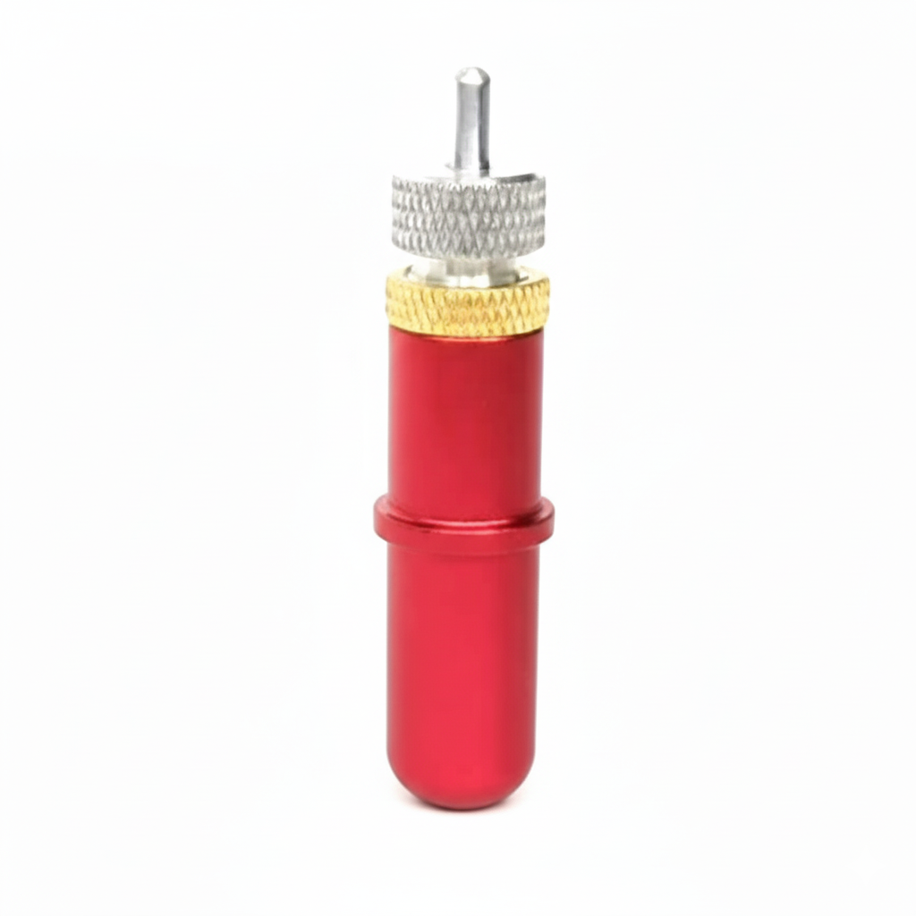
- Programmable force: the controller applies a set downward pressure, saved per material, so results are repeatable.
- Blade offset compensation: because the blade tip trails behind the holder's centre, the machine adds tiny corner moves so the blade swivels cleanly and corners stay sharp.
- Overcut: extends the cut slightly past the start point so closed shapes separate fully.
- Multi-pass cutting: repeats the path for thick materials instead of relying on extreme force.
See smart cutting technology in action
Ask for a live demo or sample cut on your own material – our team will show you what Skycut machines can do.
Automatic feeding and multi-tool heads
Automatic sheet feeding
On sheet-fed machines, an auto-feeder picks sheets from a stack and delivers them to the cutting area one at a time. Combined with camera registration, each sheet is located and cut automatically, so a whole batch can run with minimal supervision.
Dual and multi-tool heads
Two tool heads let the machine perform different operations in one job – for example, creasing fold lines and then cutting the outline of a box, or kiss cutting stickers and fully cutting the sheet border. This removes extra steps and the errors that come from moving material between processes.
.webp)
Intelligent cutting software
Hardware does the cutting, but software decides what to cut and how. Key capabilities include:
- Design import: works with CorelDRAW, Illustrator, PDF and other vector files.
- Contour generation: creates cut lines around printed artwork, with offsets for bleed.
- Registration marks: adds and positions marks for the camera automatically.
- Tool assignment: maps lines to cut, kiss cut, crease or pen tools.
- Nesting: arranges shapes closely to reduce material waste.
- Path optimisation: orders cuts to reduce travel time and keep material stable.
- Job and material presets: saves settings so repeat jobs and materials cut the same every time.
Smart cutting technology glossary
| Term | Meaning |
|---|---|
| CCD camera | Image sensor used to locate registration marks and printed features. |
| Registration marks | Printed reference points that tell the machine where the design is. |
| Contour cutting | Cutting around the outline of printed artwork (print-and-cut). |
| Encoder | Sensor that reports motor position for closed-loop servo control. |
| Blade offset | Distance between the blade tip and holder centre, compensated at corners. |
| Cutting force | Downward pressure applied to the blade, usually measured in grams. |
| Kiss cut | Cutting the top layer while leaving the backing liner intact. |
| Overcut | Extending a cut slightly past its start so shapes separate cleanly. |
| Nesting | Arranging shapes efficiently on the material to save waste. |
Smart cutting technology in Skycut machines
| Technology | Skycut machine |
|---|---|
| Camera contour recognition | Skycut C24 / CX24 |
| Servo motor motion control | Skycut VH-24 / VH-48 |
| High force (up to 2000 g) & dual independent heads | Skycut D24 / D48 |
| Automatic sheet feeding & dual head cut + crease | Skycut A3 Max 5 |
| Flatbed cutting for rigid material | Flatbed & Exclusive Series |
Want the business side of the story? Read smart cutting solutions, digital cutting solutions and cutting machine insights.
Frequently asked questions
Final thoughts
Smart cutting technology brings together vision, precise motion, controlled blades, automation and intelligent software so that cutting becomes accurate, fast and repeatable – with far less manual effort. Understanding how it works helps you choose the right machine and get the best results from it every day.
.webp)
.webp)
.webp)